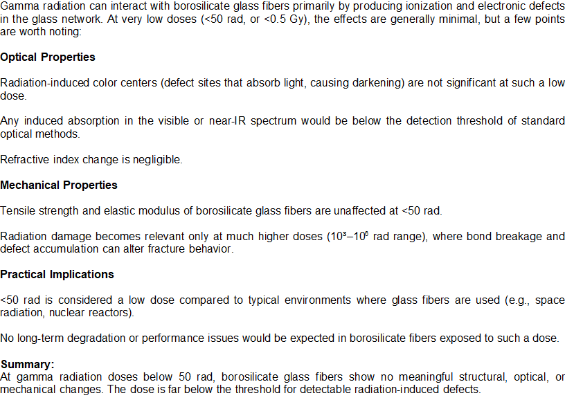
Threshold dose Levels in Borosilicate Glass Fibers
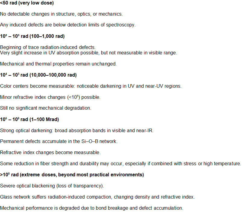
Threshold dose Levels in Borosilicate Glass Fibers
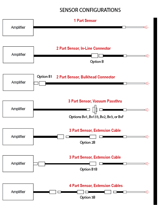
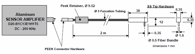
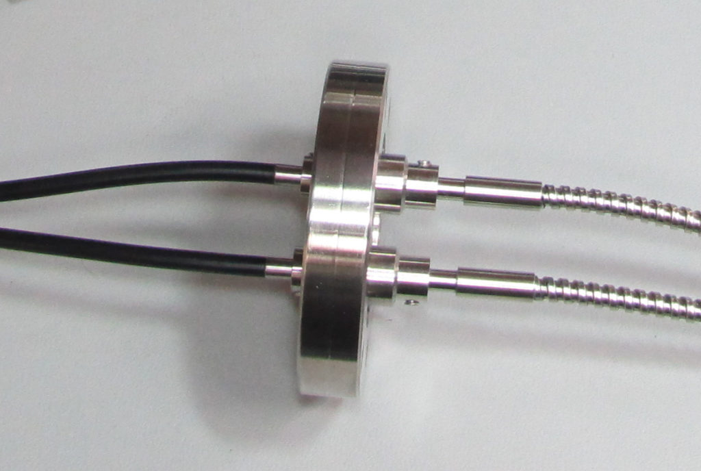
Philtec Fiber Optic sensors can make displacement measurements inside of mechanisms, machinery and vacuum chambers. To gain access to the measurement locations, Fiber Optic cables may be connectorized for the probe tips to be separated from the electronics. In some complex applications, more than one joint may be required for the installation and removal of the sensor systems. An illustration shows sensor configurations with as many as four parts that have been made and are available for some of Philtec’s sensor products. Contact our application engineering team to see if one of these systems can work for you…sales@philtec.com
The previous App Note ‘Bending Light’ showed that the light beam emitted from a fiber optic probe can be redirected to a different emission angle by polishing the fibers at an angle to the probe axis.
A new customer wants to measure turbine speed by sensing the passage of 1 mm thick blades.
THE PROBLEM: Access to the blades can only be made at a 50° angle to the blade tip surface. And, we’re not sure if the blade can be sensed at that angle
TEST PROBE
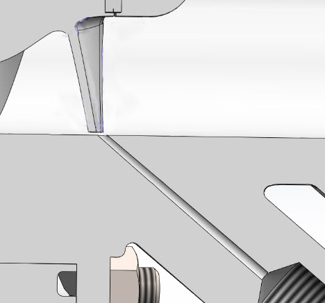
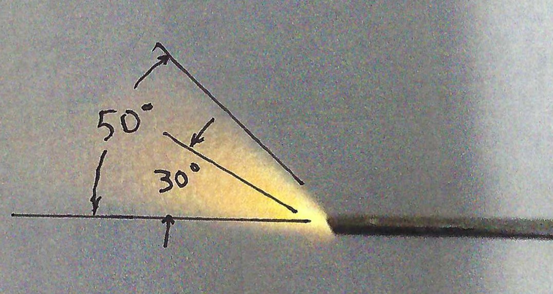
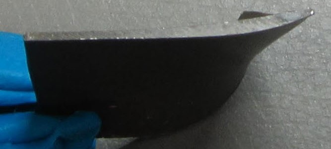
A 1.5 mm diameter test probe was made with the fibers polished to a 30° angle. When the fibers were illuminated, the emitted light beam filled a 50° cone.
A 1 mm blade was placed on a linear stage and mounted at 30° and 50° angles to the test probe.
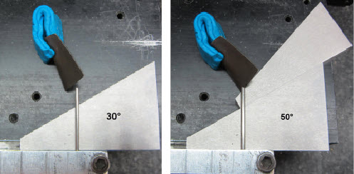
The probe output was recorded as the blade moved past the light beam of the probe.
30° Angle : Max/Min = 9 ….. 50° Angle : Max/Min = 4.4
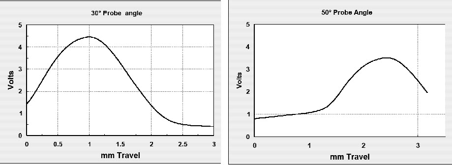
Angle polished probes can detect turbine blade passage up to a 50° access angle.
Through the years, we always appreciate customers telling us the sensors have been successful in their application. Here is our latest testamonial.
Dear Philtec workers,
We are pleased to inform you that recently Surface Technologies Research Group from Mondragon University has published a research article called “On the Role of Contact and System Stiffness in the Measurement of Principal Variables in Fretting Wear Testing” featuring a Philtec model RC90. Your sensor was the cornerstone to develop a state of the art fretting tribometer for thin steel wires.
The research article is available @ https://www.mdpi.com/1424-8220/20/15/4152/htm and is an open access article.
Magnetic Field Exposure requires non-magnetic materials. By jacketing the fiberoptic cable in non-metallic materials, and by constructing the sensor tip from non-metallic or non-magnetic materials, Philtec sensors can be configured to perform measurements in very high magnetic fields. Successful applications to 12 Tesla have been made.
We recently delivered this sensor; a model D20 high-frequency sensor for 2 Tesla exposure.
This short video highlights Standard and Customized Sensors. These devices are commonly inserted/installed into equipment or machinery that may present extreme conditions to the probes. Most applications require some customization of the probes and fiber optic cables. Philtec engineers optimize custom sensor designs to achieve best performance in their application.
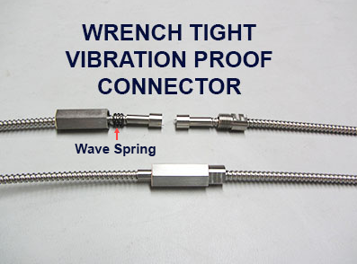
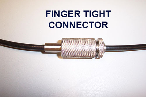
For applications where probes and fiber cables are exposed to high vibration levels, we recommend use of a wrench tight connector to make the connection vibration proof.
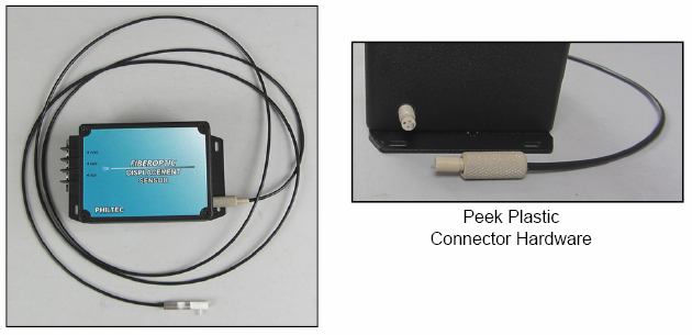
Where it is desirable to be able to separate the sensor electronics from the measuring probes, fiber optic cables can be connectorized using a simple knurled finger tight design. And damaged tips can easily be replaced.
There are other reasons why the cable could be connectorized:
PROBLEM
Quartz fibers have excellent transmission over long lengths, but they are very expensive and usually cost prohibitive. A recent customer asked for a model D171 sensor with 45 meter length for displacement measurements in vacuum and high magnetic field.
SOLUTION
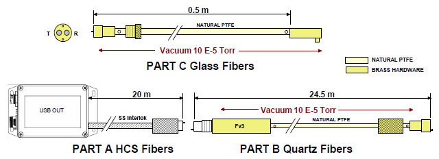
A 3-piece cost saving system was devised where only nineteen 200µm quartz fibers were used to illuminate 10% of the model D171 probe area.
Part A – Two Ø 1000 µm Hard Clad Silica Fibers, 20 m long in air
Part B – Two Ø 1000 µm Bundles of Ø 200µm Silica/Silica (Quartz) Fibers, 24.5m long in vacuum
Part C – Ø 4320 µm D171 Glass Fibers, 0.5 m long in Vacuum
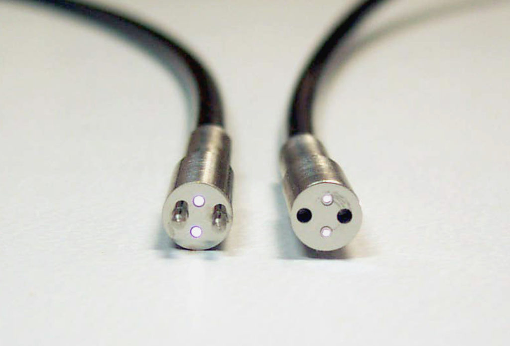
Part A has two Ø1000µm fibers at the connector interface:
Part B Ø1000 µm fiber bundles each have 19 fibers at the connector interface:
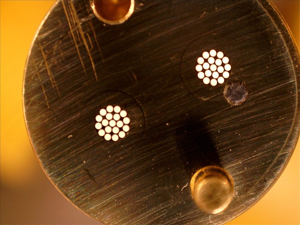
one transmits light and one returns reflected light.
Part B transmit fibers were randomly mixed with Part C glass fibers. Although Part B fibers illuminated just 10% of Part C fibers, this D171 sensor calibrated to an acceptable 70 mm displacement range. And therefore, the system cost was much lower than it would otherwise have been if all of the D171 fibers had been illuminated by quartz fibers.